
This webpage from iaa.csic.es is no more maintained and kept for historical purpose only. Please click HERE to browse the new PANIC webpages at caha.es for the camera updated with a new 4K sensor
Cryostat and Mechanisms
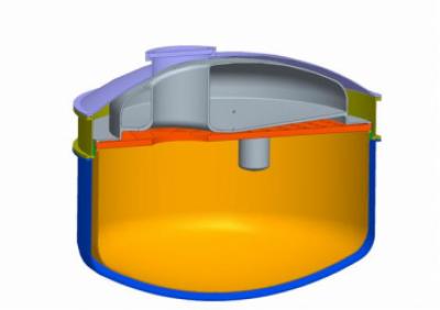
Cryostat
Due to background radiation the local temperature inside the shield should not exceed 100 K. This is also valid for local spots like cable feed-throughs or motors. Temperature changes should be in a range that the tolerances of the optics are met. The detector has a working temperature of about 77 to 80 K which has to be investigated. The required stability is ±0.1 K. Warm up and cool down of the detector has to be slower than 0.5 K/min.
The cryostat is a nitrogen bath cryostat with a large vessel to cool the complete structure. To reduce LN2 consumption and thermal gradients we use 30 layers of multilayer insulation (MLI) on the cold surface. This should reduce the heat load from radiation to about 5 W/m2. For a constant detector temperature we use a second small LN2 vessel exclusively to cool the detector. For weight reduction we will use dished ends on the vacuum can instead of flat thick walled plates.
|
|
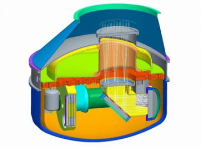
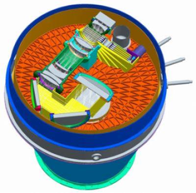
Mechanism
The optical elements of PANIC are arranged in two groups. These groups are mounted directly to the cold bench. The first assembly (optics group 1) consists of the mirrors M1 to M3, the lenses L0 to L4 and the cold stop. The filter unit has four filter wheels with 6 positions each. So in total 20 filters (or 19 filters and a dark) can be installed. The opto-mechanics is completely encapsulated to minimize stray light effects from the bench and the cold shields. Both optics assemblies do not touch each other. An optical labyrinth ensures light tightness between them. The arrangement scheme of all optical elements of PANIC is shown in next figures.
|
|
|
|
For more details, you can see the Mechanical FDR or Mechanical As-Built Design Report.
Latest News
| Title |
Date |
|---|---|
| New detector at CAHA | 30-Sep-2019 |
| SEA Award | 21-Jun-2019 |
| New detector ordered | 15-Sep-2018 |
| New publication: "PANIC: A General-purpose Panoramic Near-infrared Camera for the Calar Alto Observatory", M.-C. Cárdenas Vázquez et al, PASP 130, 984 | 10-Jan-2018 |
| Instrument acceptance | 30-Nov-2017 |
- 1 of 4
- next ›